
Purpose-built Papa Alpha tools help mechanics inspect flight-control travel and rigging against the applicable Piper maintenance data.
Ask your IA: “Do you have the rigging tools to inspect the travels of my flight controls at this annual inspection?” Most owners assume the answer is yes. In practice, many shops do not make or buy the model-specific tooling needed to measure Piper flight-control travel and neutral positions accurately.

The applicable Piper maintenance manual establishes the procedures and specifications for rigging the flaps, ailerons, stabilator, and rudder. Some measurements are taken from the wing and stabilator chord or from the vertical-stabilizer centerline. Without purpose-built tooling, obtaining accurate, repeatable measurements can be extremely difficult.
Papa Alpha tools are produced from Piper manual drawings and give mechanics a practical way to measure control travel and rig flight controls to the applicable factory specifications. Confirm every tool's applicability to the aircraft model and serial number before use.
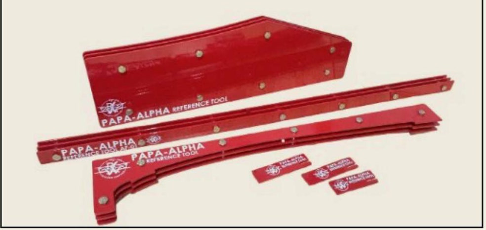
Step One: Flaps
Rigging the flaps requires the flap-and-aileron rigging tool to be placed at the outboard flap station while the pushrod that actuates the flap is adjusted, if necessary, to achieve contact between the tool at all three points—two on the wing and one at the flap's trailing edge.
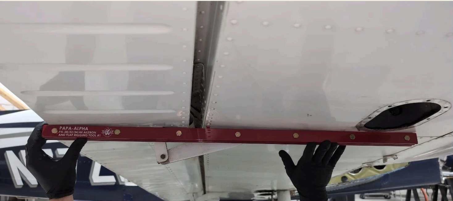
Step Two: Ailerons
The applicable manual sequence calls for the flaps to be rigged before the ailerons are adjusted. Block the forward portion of the bellcranks against the nearest rib with the bellcrank rigging tool, block the control column in the forward position, and use the applicable aileron tools to establish the neutral position independently. If adjustment is required, follow the applicable maintenance data and measure travel from the established neutral position.
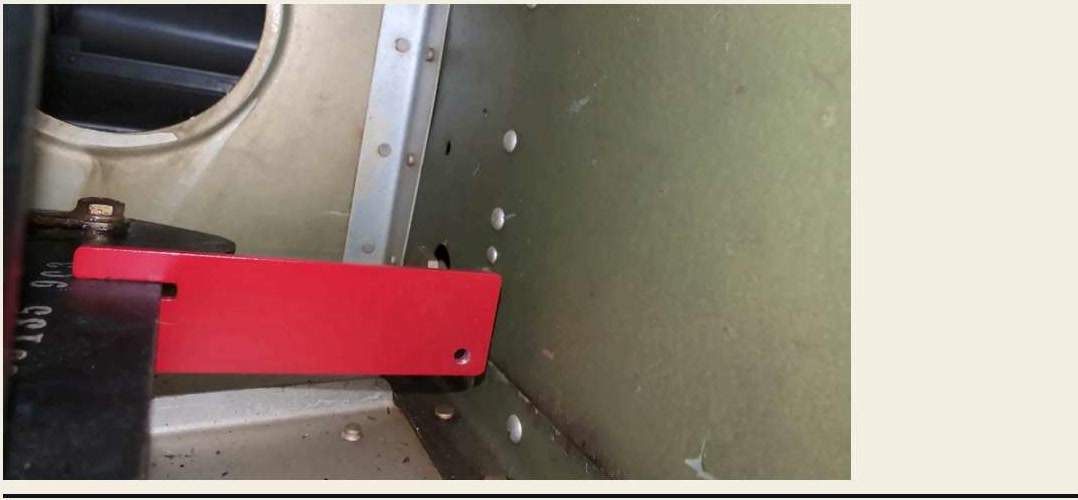
Step Three: Stabilator
Before stabilator rigging, level the aircraft laterally across the spar-box reference and then longitudinally at the two leveling screws below the left-front side window, as specified by the applicable manual. Place the stabilator tool against the leading edge with one end resting on top of the stabilator at the inboard edge of the stabilator fairing. Move the stabilator until the tool is level; this establishes neutral. Remove the stabilator trim tab to the neutral position, then take the required stabilator and trim-tab measurements.
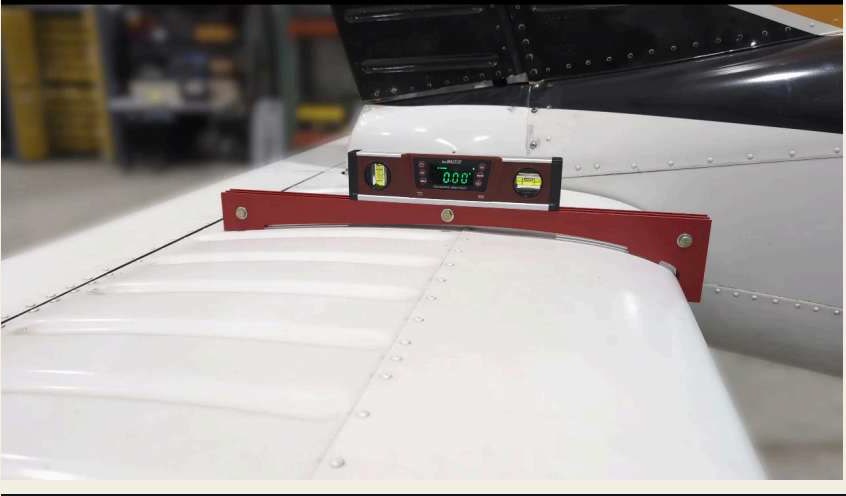
Step Four: Rudder
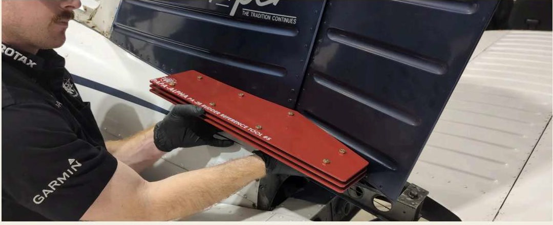
Place the rudder rigging tool against the base of the vertical stabilizer and move the rudder to the stop on each side, visually checking contact between the tool and rudder. If there is a gap, check rudder travel and stop adjustment against the applicable maintenance data before making any adjustment.
Built for Mechanics
Papa Alpha rigging tools are made for mechanics by mechanics. Tools and kits are available for specific aircraft series and serial-number ranges, and no longer apply if mechanics or IAs have modified them. Confirm current applicability before use.
Browse Papa Alpha tools or contact the RWAS avionics and maintenance desk at (605) 299-8178.
Before Return to Service
Always verify cable tensions against the applicable specifications after flight-control adjustments. Consult the Aircraft Maintenance Manual for model-specific procedures; the generalized procedure in 14 CFR Part 43 Appendix D is not a substitute for the complete maintenance instructions. Always consult current maintenance data for the complete steps, inspections, limits, and return-to-service requirements.